Users are allowed to edit their own TCP/IP settings, but one user complains she is unable to edit the settings in her TCP/IP configuration. What should you do?
What methods enable you to create shared network folders?
Right-click a folder in My Computer or Windows Explorer, select Sharing and Security, click the option button Share This Folder, and click OK.
Open the Rundialog box, type fsmgmt.msc, press OK, right-click the Shares node, and click New File Share. Follow onscreen instructions for the Create Shared Folder Wizard. Note: Simple File Sharing must not be enabled to create a New File Share using this command.
Open the Computer Management console, expand Shared Folders, right click the Shares node, and click New File Share. Follow the on-screen instructions for the Create shared Folder Wizard. Note: Simple File Sharing must not be enabled to create a New File Share using this command.
Open a command promptwindow. Type Net Share share_name=x:\folder_name, where share_name represents the name you want to assign to the shared folder, x: represents the drive letter where the folder resides, and folder_name represents the actual name of the folder.
Using group policies, you need to provide a way for the user to be able to reset the password and view the Welcome screen rather than be logged on automatically to her computer running Windows XP. The computer is part of a workgroup, not part of a domain. How do you accomplish this task?
The Michael Meyers CompTIA Network+ All-in-One Exam Guide, featured on the left, is study guide I am using to prepare myself for the CompTIA Network+ Exam. It is an excellent study guide, and easy to understand.
I will attempt to summarize some points that may be helpful to you in understanding TCP/IP. And, more importantly, will be here as a reference guide.
In the beginning, there were several different networking protocols: Novell Netware IPX/SPX, Microsoft NetBIOS/NetBEUI, Apple's AppleTalk, and UNIX's TCP/IP. We all know now that UNIX's TCP/IP is the standard protocol that is predominately used in today's networks.
How does the computer know where to send its data? Data is contained in frames. In a small network, a computer sends a frame by broadcasting to MAC address FF-FF-FF-FF-FF-FF. This is the universal MAC address for broadcast. This broadcast goes out to all of the computers in the network. You can't do that on the Internet. It's too much. This is where IP addressing comes into play. Just as every computer has a unique MAC address, every computer has a unique IP address, and they are grouped together for each network logically, so you can distinguish individual networks.
IPV4 is a 32-bit value of ones and zeros. This is binary which is the base-2 number system.
An example is:
11000000101010000000010000000010
These ones and zeros are converted to decimal numbers to make it easier for us to remember. The computer and router have no problem reading this binary address, but, we humans do have a problem. So we need to convert it to decimal. To do this, first you break up the 32-bit value into 8 bits.
11000000 10101000 00000100 00000010
Each of the 8 bits are then converted into a decimal number separated by dots.
Binary is the base-2 number system, so an easy way to convert to decimal is to write out the decimal value for each bit:
128 64 32 16 8 4 2 1
Let's take the first set of eight binary bits, 11000000. For each bit that has a 1, write down the corresponding decimal value. In this case, it is 128. The next 1 that you see is in the 64 position. Add that to the 128, and you get 192.
Now let's take the next set of binary bits, 10101000. The first 1 is 128. The second 1 is 32. The third 1 is 8. Notice how I simply lined the binary digits up under the corresponding decimal, from left to right. Now add the 128+32+8. You get 168.
So far we have 192.168. Next take the next set of 8 bits, 00000100. The 1 is i the 4 position. So, we have 192.169.4. The next set of 8 bits is 00000010. That 1 is in the 2 position.
So the IP address is 192.168.4.2.
Every Operating System comes with a utility to determine both the MAC address and the IP address of your computer. In Windows, the command line utility is IPCONFIG /ALL. In the MAC/UNIX/LINUX world, the command line utility is IFCONFIG. You can also find out the IP address on the MAC by going to the Network utility, click on the Advanced tab, then the TCP/IP tab.
Each computer in a Local Area Network must have some way to indicate it is a member of that particular network. For instance, if you have a Class C network address and an IP address 192.168.4.2, 192.168.4 is the network id and 2 is the host id. The subnet mask is 255.255.255.0.
When a TCP/IP LAN needs to connect to another TCP/IP LAN, it has to have a router. The router has to have an IP address on the network. The router's IP address is known as the default gateway.
Most ISPs give the router the lowest host IP address for the network. In this example, that is 192.168.4.1. Each router has a routing table that tells it where to send incoming packets. The method a router uses to determine if the packet needs to go on the LAN, or, to a computer on the WAN, is the subnet mask.
If a computer needs to get a packet on the LAN, it simply sends out a broadcast address to get the other computer's MAC address. If the computer needs to get a packet on the WAN, in other words outside of your local area network, it sends the packet to the default gateway. How does the computer know whether the packet goes on the LAN or the WAN? The subnet mask tells the computer what portion of the of the IP address is the network id. 255 converts to 11111111 in binary. If the subnet mask is 255.255.255.0, then that tells you the first three nodes of the ip address is the network id. The computer compares the destination id to its own IP address using the subnet mask. If the network ids match, it knows the packet is local. If not, the packet is on the WAN.
If it is a local call, the computer (we will call it COMPA) sends out an ARP broadcast, to determine the MAC address of COMPB. COMPA sends out an ARP packet that contains its own IP address (in this case 192.168.4.2), the IP broadcast address (in this case 192.168.4.255), it's own MAC address, and the Ethernet broadcast address of FF:FF:FF:FF:FF:FF). COMPB's MAC address responds to the ARP by sending an ARP response containing COMPB's MAC address.
When COMPA has COMPB's MAC address, it starts sending packets. To show Windows's current ARP table, open a command line and type: arp -a
When a computer wants to send a packet to an IP address on an outside LAN, it sends the packet to the default gateway, in this case 192.168.4.1. It still sends out an ARP, but to the default gateway. Once the computer gets the default gateway's MAC address, it starts to send out the packets.
Usually subnet masks are represented by using a / character followed by the number of ones in the subnet mask. An example is 192.168.4.2/24.
An organization called the Internet Assigned Numbers Authority (IANA) assigns IP addresses in contiguous chunks called class licenses. The IANA presides over a number of Regional Internet Registries (RIRs) and the RIRs distribute IP addresses to large ISPs. Most end users get IP addresses from their ISP.
A Class A license has a subnet mask of 255.0.0.0 and the first octet that defines the network id starts between 1-126. The first binary octet of a Class A license always begins with 0 (0xxxxxxx). Potential number of hosts 16,277,214.
A Class B license has a subnet mask of 255.255.0.0 and the first and second id define the network id. The first octet decimal value is 128-191. The first binary octet of a Class B license always begins with 10 (10xxxxxx). Potential number of hosts 65,534.
A Class C license has a subnet mask of 255.255.255.0 and the first three octets define the network id.
The first octet decimal value is from 192-223. The first binary octet of a Class C license is always 110 (110xxxxx). Potential number of hosts 254.
Class D is reserved for Multicast. The first octet decimal values are from 224-239. The first binary octet of a Class D license is always 1110 (1110xxxx).
Class E is a Reserved license. The first octet decimal values are from 240-255. The first binary octet for a Class E license is always 1111 (11110000).
IP Class licenses eventually ran out and didn't work well for most organizations because the number of hosts needed varies for each organization. A new method was developed called Classless Inter-Domain Routing (CIDR). This is where subnetting comes into play. CIDR is done by the ISP. IANA assigns a block of addresses to the ISP, and the ISP subnets the block into multiple subnets, and then passes out the smaller subnets to customers.
To subnet, you take the existing /8, /16/, and /24 subnet mask and extend it one bit at a time until you have the number of subnets you need. First, convert the subnet mask to binary and remove the dots. For example, say you have a subnet mask of 255.255.255.0. Convert it to binary.
11111111111111111111111100000000
Change a 0 to a 1 so that you have 25 ones instead of 24.
11111111111111111111111110000000
The subnet mask becomes /25
The videos below do a great job of explaining subnetting based on the Magic Number Theory and how to determine the number of subnets needed, hosts, broadcast ids. They are the best I've seen!
The Windows Sysinternals website is part of Microsoft Technet and contains freeware for managing and troubleshooting Windows operating systems. Sysinternals was started by Microsoft developers Mark Russinovich and Bryce Cogswell. Sysinternals became part of Microsoft in 1996.
The Mike Meyers CompTIA Network+ All-in_One Exam Guide Fourth Edition is an excellent guide book you can use to study to obtain the Network+ certification. Click on the adjacent Amazon link for a detailed synopsis of the book and an easy way to purchase it.
Below, are a few notes I have taken during my course of study for the Network+ certification that you might find useful.
TIA/EIA standards are the rules for structured cabling. The organization BICSI (Building Industry Consulting Services, International), www.bicsi.org, provides information about structured cabling and provides certifications for the cabling industry.
Cables run horizontally from the telecommunications room to the PC work areas. This is called horizontal cabling. A single piece of horizontal cabling is called a run. The area on the opposite end of the cabling is called the work area (where the PC usually is).
Horizontal cabling is the cabling that runs from the telecommunications room to the work area. The cabling is usually CAT 5e or better UTP cable, solid core or stranded core, very inexpensive and versatile. Solid core has a single solid wire and is thicker. Stranded core is a bundle of tiny wire strands and is more pliable. Solid core will break if handled incorrectly, but is a better conductor, than stranded core. Stranded core is much easier to handle than solid core. Horizontal cabling should always be solid core because it will be installed in the ceiling and there is less risk of the cable being bent, or stepped on, or damaged in some other way. Plenum cabling is used between walls because it is fire resistant.
The telecommunications room is also known as the intermediate distribution frame (IDF). Because this is where all of the cabling comes together, the telecommunications room can develop into a messy monstrosity overtime if care is not taken to systematically organize and label the cables when a change is made.
You will need an equipment rack in a telecommunications room. A patch panel is a box used to contain the cable connections with the short end of the cable going into the front and the longer end coming out of the back. UTP cables connect to a 110 punchdown block in a structured cabling system using a punchdown tool. The metal-lined grooves for the individual wires and the punchdown tool forces the wire into the groove. Place a label on the patch panel to identify each cable. Patch panels come in varying types, for UTP, STP, or fiber ports.
Install the patch panel, and connect the ports to the switch using a patch cable. Patch cables are UTP stranded cables, and easier to handle than solid core.
In the work area is the wall outlet that consists of one or two female jacks. This jack is the termination point for the network cable. The PC is connected to the wall outlet with a stranded patch cable. It is a good idea to label the wall outlet so that the wall outlet shows its position on the patch panel.
A demarc is the term used to describe the location where connections come into the building from the outside. This location marks the dividing line of responsibility for network functionality. The internal side of the demarc is your responsibility. The other side of the demarc is the ISPs responsibility, or the company that provides the upstream service to you.
In your home, the DSL or cable modem is your demarc. This is the line between your side and the service provider. In the office, the demarc is more difficult to determine because of the increased layout complexity. Most NIDs (Network Interface Device) today are known as smart jacks, because they enable the ISP to determine if the customer has disconnected from the NID. Smart jacks also do remote loopback-good for loopback testing when the other end of the connection is some distance away.
A cable drop is the location where the cable comes out of the wall. Before you map your runs, you should obtain a floor plan. There are external raceway products that adhere to the walls. Raceways are good for older buildings where you don't want to open up the walls.
The room must be placed in a spot that won't require cable runs of more than 90 meters. Plan the types of cable and runs needed. Calculate your cable runs and add 25%. Measure the vertical drop from the ceiling to the wall jack and ad 18". Minimize sharp bends.
Make sure your telecommunications room has its own dedicated power circuit.
Have a wiring map.
Hire a certified company to do your wiring tests.
Make sure the room has low humidity and is well air-conditioned.
Remember heat is the enemy of computer equipment. Keep the telecommunications room cool!
Make sure the telecommunications room is secure.
Local codes and TIA/EIA and the National Electrical Code (NEC) contain the rules of how to pull cable through a ceiling. Each cable must be tested to ensure every connection works as desired and can handle the speed of your network. TIA/EIA has certain standards for testing cable runs. Testing should be done by a professional cable installer.
There are a few inexpensive tools a tech can use to test connections. A multimeter tests continuity and is done by placing the probes on either end of the cable. Set the multimeter to its continuity setting or to Ohms. Electrical impedance is measured in ohms. With Ohms, if you have a connection, you get zero Ohms, and if you don't have a connection, you get infinite Ohms.
A TDR, Time Domain Reflectometer, tests continuity and includes the additional capability to determine the length of the cable. Some have a loop back tester to work with installed cables. Good testers can test crosstalk and attenuation.
Twisted pair (TP) cable connections have four pair of wires. Each pair is twisted to prevent crosstalk or EMI (Electrical Magnetic Interference). Highly rated wires have more twists. Crosstalk is when a signal is sent down one of the wire pairs, and the other pairs pick up some of the signal. Near-end crosstalk (NEXT) is when an electronic detector device, picks up on the signal from the other pair on the end closest to the device. If you repeat the test, sending the signal down the pair of wires on the far end of the connection, picking up a signal from the other wire, you have far-end crosstalk (FEXT).
Attenuation is when the signal progresses down a piece of wire and becomes steadily weaker. This happens as the cable run gets longer. The maximum run for TP is 100 meters.
The process of verifying that every cable run meets the TIA/EIA standards requires testing tools, called cable certifiers. Certifiers can do the testing and generate a report to show the customer. Fluke networks, www.fluke.com, has electronic test tools and software.
Most fiber optic runs use only two cables, so they don't experience crosstalk/EMI. However, they do break and require an OTDR (optical time domain reflector). OTDRs are used to verify impedance and cable termination. OTDRs tell you exactly how far down the cable to look for the break. Fiber certifiers tests fiber optic runs to ensure a fiber will carry the designated signal speed.
The three big issues with fiber are attenuation, light leakage, and modal distortion. Light diffuses over distance, causing attenuation, when the light signal spreads and the signal weakens. Light leakage occurs when if the cable is bent too much, exceeding the maximum bend radius. Multimode fiber has the problem of model distortion. The light is sent out in different modes, some light shoots straight, and some bounce back and forth at a sharp angle down the fiber.
A NIC provides the physical connection between a workstation and the network infrastructure. All UTP Ethernet NICs use the RJ-45 connector, and the cable runs from the NIC to the hub or switch.
There are many different types of fiber-optic NICs. Check the documentation to determine what you need and opt for the multispeed cards. You need to have the right connectors and protocol. The MAC address is coded into all NICs.
Most PCs come with built-in NICs. Some laptops have NICs located on the motherboard, which would require a motherboard replacement. Most PCs come with two types of expansion slots, the Peripheral Component Interconnect (PCI) type and the PCI Express (PCIe). PCIe is the newer type. You can get NICs with a USB or PC Card connection. USB is convenient, but has a maximum speed of 480 Mbps, and the PCMCIA/PC card is only good for laptops.
After you physically install the NIC, installing the NIC driver into the OS is the next step. Verify the computer has the NIC and is in good working order. On Windows, check Device Manager. Ubuntu Linux has the Network applet, and Macs have the Network utility in System Preferences.
Bonding is when you use multiple NICs for a single machine. This is also called link aggregation. Bonding or link aggregation will at least double the speed between a machine and switch.
UTP NICs have light-emitting diodes (LEDs) that give info about the NIC's link. These lights give you pointers about what is happening and is one of the things to check when you can't get a connection to the network. Be sure to check the documentation for the meaning of the lights. Switches and hubs also have link lights. A very important light is the activity light. The activity light indicates the network is functioning. So, even if the link lights look good, if you are doing work on the computer and the activity light is not flckering, you know something is wrong.
Fiber-optic NICs are much more difficult to diagnose. Many fiber-optic NICs don't have lights. An optical tester enables you to check the connectors on a fiber-optic NIC.
If you receive the message, "No server is found" error, this is might mean you have a physical problem with the network. First check for software errors. However, a bad NIC can generate this message, so you should use the utility provided with your OS to verify the NIC works. Some NICs have diagnostic software you can run.
If you believe the problem is hardware, first check the link lights on the NIC and switch. If they are not lit, then you know the cable might be disconnected. You can always check the network icon in your OS to determine if you have a connection, and go from there.
Make sure other people can access the problem server. Inspect the cable running from the PC to the outlet. If that doesn't work, try another outlet. Most network disconnect problems occur in the work area, but, if you have tested and determined the problem is not in the work area, it could be time to test the horizontal cabling run. A midrange tester with TDR like the Fluke Microscanner can be used to determine whether and where the cable is disconnected.
If your UPS comes on too often, it might be a good idea to install a voltage event recorder. A voltage event recorder plugs into your power outlet and tracks the voltage over time. Because heat is an issue with electronic equipment, your telecommunications room should have a temperature monitor. Tracing cables will eventually become a need and a toner is a good device to have for that. The toner is really a tone generator and a probe. The tone generator connects to the cable using tiny hooks and sends an electrical signal along the wire at a certain frequency. The tone probe emits a sound when it is placed on a cable connected to the tone generator, indicating the right cable.
A good cable tester and a good toner are the most important tools used by a network technician whose job it is to support a network.
Questions
1. Which cable should never be used in a structured cabling install? Coax
2. Which type of network is a dedicated line allocated for the transmission of data between two network nodes? Circuit switching
3. What enables you to use multiple NICs together in a computer to achieve a much faster network speed? Bonding
4. The CAT 5e rating defines how many pairs of wires in the cable? 4
5. What organizes and protects the horizontal cabling in the telecommunications room? Patch panel
6. What are patch cables used for? They are used to connect PCs to outlet boxes, and, to connect the patch panel to the hub.
7. Which network technologies use UTP cabling in a star topology? 10BaseT and 100BaseT
8. Tina needs to increase network throughput on a 10BaseT network that consists of 1 hub and 20 users. What is the most inexpensive hardware solution? Replace the hub with a switch.
9. What two devices together enable you to pick a single cable out of a stack of cables? A tone generator and a tone probe work.
10. Rack-mounted equipment has a height measured in what units? U
11. What is the most popular type of cabling currently used? Fiber
12. What device helps to prevent network collision by not allowing data to be broadcast? A switch
13. What cable type with a single copper wire is used for sending and receiving data? Coaxial
14. What is the lowest grade of cable to run 1000BaseT? UTP CAT5e
15. What is the maximum distance to run UTP cable? 100 meters. Thin-net coaxial is 185 meters. Multimode fiber is 400 meters.
The Mike Meyers CompTIA Network+ All-in-One Exam Guide Fourth Edition is an excellent guide book you can use to study for the Network+ certification. Click on the Amazon adjacent Amazon link for a detailed synopsis of the book and an easy way to purchase it.
Below, are a few notes I have taken during my course of study at New Horizons for the Network+ certification that you might find useful.
The Ethernet standard dominates networking technology today and has been around since Xerox developed it in 1973. The Ethernet is standardized as 802.3 and is based on the bus topology using twisted pair wiring.
Every version of Ethernet uses either unshielded twisted pair (UTP) or fiber. Every version of Ethernet uses a hub or a switch, hubs being very rare today.
Only 10 megabit and 100 megabit Ethernet use a hub.
1 gigabit and 10 gigabit Ethernet networks must use a switch.
Every version of Ethernet has a limit of 1024 nodes.
The maximum distance from the switch or hub to the node for UTP Ethernet is 100 meters.
Since 1990, Ethernet uses a hybrid star-bus topology and the hub acts like nothing more than a repeater. These ethernet hub networks use half-duplex and CSMA/CD for transmitting data. Every network breaks up data into pieces, called frames. This prevents a computer from hogging the shared cable. The data frames contain MAC addresses to identify the sending and receiving computer. CSMA/CD stands for carrier sense, multiple access/collision detection and determines which computer can access the wire and when. CSMA/CD is an 802.3 IEEE standard.
A basic Ethernet frame contains the following: the preamble, the MAC address of the receiving computer, the MAC address of the sending computer, the data length, the data itself, a pad, and a CRC (cyclic redundancy check, i.e., a frame check sequence).
Preamble: 64-bit series of alternating ones and zeros that end with 11. The preamble lets the receiving computer know a data frame is imminent.
MAC address: Every NIC has a unique MAC address. The hub sends out a copy of the frame to each computer on the wire. The computer with the matching MAC address recognizes the frame, while the other computers ignore it.
Length: A frame can carry 1500 bytes of data in a frame and the length field tells the receiving computer how many bytes of data are coming.
Data: The data part of the frame actually contains the data and also the IP address.
Pad: A pad is added to the frame if the data is less than 64 bytes.
CRC: The frame check sequence is like a check sum that enables the system to verify if all of the data was received. The sending computer computes the CRC by using a special mathematical formula and attaches the result to the frame. The receiving computer does the same thing, and if the CRC does not match, the receiving machine lets the sending machine know so that the data can be retransmitted.
The earliest version of Ethernet was 10Base5 and 10Base2, now obsolete. 10BaseT was created in 1990 and became the most popular networking standard in the world.
The number 10 refers to 10 Mbps and the word Base refers to baseband. The letter T refers to UTP cabling. 10BaseT requires the use of CAT3 or higher. CAT3 is a two pair wire, UTP (unshielded twisted pair) cable. One pair of wire sends data and one pair receives data. 10BaseT only requires two pair of wires, however, most people uss the four-pair wire to ensure against future technological advancements. The RJ-45 was also introduced at this time for 10BaseT. Each wire in the cable attaches to a pin in the RJ-45 connector. The real name for an RJ-45 is 8P8C, however, everyone calls it the RJ-45 connector. The TIA/EIA (Telecommunications Industry Association/Electronics Industries Alliance) defined the standard used called the TIA/EIA 568A and 568B.
10BaseT has a distance limitation of 100 meters. A 10BaseT hub can connect no more than 1024 computers.
10BaseFL was introduced a few years after 10BaseT. 10BaseFL is the fiber-optic version and transmits data using pulses of light. 10BaseFL signals can travel much further than 10BaseT electrical signals. The maximum length is up to two kilometers, and is immune to electrical interference (EMI). 10BaseFL uses multi-mode fiber-optic and uses either an SC or ST connector.
Media converters can be used to connect different kinds of cable, such as 10BaseT and 10BaseFL. Once the network expands in size, you need a way to connect efficiently. A bridge can be used to connect hubs or an uplink port or crossover cable.
With an uplink port, two hubs can be connected using a straight-thru cable. In order to connect two hubs, insert one end of the cable into the uplink port and the other end into the other regular port. You must daisy chain the ports, to connect multiple hubs.
Hubs can also connect using crossover cables. A crossover cable reverses the sending and receiving pairs on one end of the cable. This allows the two hubs to hear each other.
A bridge can be used to connect two Ethernet segments. The bridge acts like a repeater, but also monitors network traffic. Bridges are mainly used in wireless networks. Switches are mainly used in wired networks to connect segments.
An Ethernet switch looks like a hub but is intelligent. The switch uses the MAC addresses, creating point to point connections. Point-to-point is when two nodes have a dedicated connection. The switch creates an electronic table of the MAC addresses and acts like a telephone operator. Speed is enhanced and there is no longer a need for CSMA/CD. All devices connected to the switch will hear a broadcast sent from any one system, essentially a broadcast domain.
Spanning Tree Protocol was something that added a bit more intelligence to the switches to take care of the problem called bridge loop. The loop happened when there were too many switches which caused an endless bridge loop.
By the late 1990s, 100BaseTX became the most popular 100 megabit Ethernet standard. 100BaseTX is referred to as 100BaseT and uses CAT 5 cables. 100BaseT has a speed of 100 Mbps, a signal type of Baseband, 100 meters distance between the hub and node, CAT 5e or better UTP cables with RJ-45 connectors, and is a star-bus topology.
In a 100BaseT network, you must have a CAT 5 cable or better. Most network cables today are at least CAT 5, so this probably isn't an issue. You must have 100BaseT NICs and a 100BaseT hub or switch. 100BaseT NICs are called 10/100 NICs, and when the NIC first connects with the network it automatically determines the hub or switch speed. If the hub or switch only does 10BaseT, then the NIC does 10BaseT. If the hub or switch does 100BaseT, then the NIC does 100BaseT. 100BaseT NICs have totally replaced 10BaseT NICs.
Most Ethernet networks use UTP cabling, but there are many that are fiber-based because UTP cabling doesn't meet the needs of the network requirements. If the property is large, the 100 meter distance limitation doesn't work. UTPs unshielded twisted pair cabling containing a lack of electrical shielding does not work if there is a lot of electrical interference. Not to mention, it is easy to tap, and if you need a secure environment, 100BaseFX fiber-optic cable is better. 10BaseFX looks just like 10BaseFL, and has a maximum cable length of 2 kilometers, and is 100 Mbps. 100BaseFX uses ST or SC connectors.
By the end of the 1990s, the IEEE approved the 1000BaseT and the 1000BaseX standards. 1000BaseX is divided into other standards such as 1000BaseCX, 1000BaseSX, and 1000BaseLX. 1000BaseT uses four-pair UTP cabling and like 10BaseT and 100BaseT, has 100 meters maximum cable length. 1000BaseT is now the dominant Gigabit Ethernet standard.
1000BaseCX uses twinaxial cable with a length limit of only 25 meters. 1000BaseSX uses multimode fiber-optic cabling, and has a maximum cable length of 220-500 meters and rely on the SC type of connector. 1000BaseLX use single-mode laser cables up to 5 kilometers, and with a repeater, the distance can be increased up to 70 kilometers. 1000BaseLX connectors look like 1000BaseSX SC connectors.
10 Gigabit and 100 Gigabit Ethernet was soon developed and standardized by the IEEE members, to satisfy the increased desire for more bandwidth. In 2006, IEEE came up with a standard for 10 Gigabit Ethernet running UTP, 10GBaseT. Unfortunately, 10GBaseT, running on CAT6 cable has a maximum cable length of only 55 meters. CAT 6a cabling enables 10GBaseT to run at a distance of 100 meters.
Questions
1. Ethernet hubs take an incoming packet and repeat it out to the connected ports.
2. What begins an Ethernet frame? preamble
3. What type of bus does 10BaseT use? Star bus
4. What is the maximum distance for an ethernet segment? 100 meters
5. When used for Ethernet, unshielded twisted pair uses what type of connector? RJ-45
6. What is the maximum number of connected segments for 100BaseT? 1024
7. Which connectors are used by 10BaseFL cable? SC and ST
8. Which network devices can use the Spanning Tree Protocol (STP)? Switches
9. What device filters and forwards traffic based on MAC addresses? Bridge
10. What is the maximum distance between the hub/switch and node for 100BaseT Ethernet? 100 meters
11. What is the type of cable and connector that 100BaseFX uses? Multimode fiber with ST or SC connectors
12. How many pairs of wires do 10BaseT and 100BaseT user? 10BaseT and 100BaseT use two wire pairs
13. What is the standard IEEE 802.3ab? IEEE 802.3ab describes 1000BaseT which is known as Gigabit Ethernet and uses four pair UTP cabling to achieve gigabit performance.
14. What is the max distance for 1000Base LX with out repeaters? 5000 meters/5 kilometers. Some manufacturers increase the distance up to 70 kilometers with special repeaters.
15. What is the big advantage of using fiber-optic cabling? Fiber is not affected by electrical magnetic (EM) interference.
16. What is the standard connector for the 10-GbE fiber standard? There is no standard. It is left up to the manufacturers.
17. How many wire pairs does 1000 BaseT use? 1000BaseT uses four pairs of wires
18. What is the maximum cable length of 10GBaseT on CAT 6? 10GBaseT on CAT 6 cables are limited to 55 meters.
3. What Windows utility is used to determine the MAC address? IPCONFIG /ALL from the command line.
4. A MAC address is known as what type of address? The physical address, a 48-bit value. It is a unique address assigned to each NIC. An example of a MAC address is 00-50-57-A4-05-0D.
5. A NIC sends data in chunks called what? Frames. Networks use frames to prevent one NIC from hogging the wire.
6. Which MAC address begins a frame? The MAC address of the receiving NIC begins a frame, followed by the sending NIC MAC address, and then followed by the data and CRC.
7. What does the CRC do? CRC stands for cyclic-redundancy check, a special bit of checking information that the receiving NIC uses to verify the data arrived correctly.
8. What layer of the OSI model controls the assembly and disassembly of data? The Transport Layer, the breaking up of data into chunks that are sent across a network and reassembled on the receiving end. Refer to the link above for a detailed explanation of the Transport layer.
9. What layer of the OSI model keeps track of a system's connections in order to send the right response to the right computer? The Session layer keeps track of a system's connections so that the right response will be sent to the right computer.
There are three different types of cables used in networking:
Coaxial (coax)
Twisted Pair
Fiber Optic
Coaxial Cable
Coaxial cable has an inner copper core surrounded by insulating material, and the insulating material is surrounded by a braided wire, that has an outside rubber insulating layer. The center wire and the braided metal shield share a common axis or centerline.
Coaxial Cables shield data transmissions from electro-magnetic interference (EMI). Lights, cable televisions, cordless telephones, microwave ovens, refrigerators, anything where the electrical current is being turned on or off, can generate magnetic fields that cause electrical current along the wire. This type of interference can disrupt transmissions on a network.
The most popular connectors for coaxial cables used to be BNC connectors.
BNC Connector
Vampire connections, sometimes called vampire taps, that pierced the cable, were also popular in early bus topology networks.
Coaxial cable used today is mostly used for connecting to an Internet Service Provider (ISP) via cable modem. The same type of cable is used to connect televisions to cable boxes and satellite receivers. An F-type connector that screws on is used to connect the cable.
F-type Connector
Cable modems connect using RG-6 type cables, predominately used in cable television. Coax cables have an RG rating. The U.S. military developed the ratings during WWII to provide a quick reference for the different types. The most important measure of coax cabling is its Ohm rating. The Ohm rating is the characteristic impedance or electrical resistance of the cable.
If you have a situation where you need to split a single coaxial cable, coaxial splitters can be used to connect two cables together using a barrel connector. This allows you to add some distance to a connection.
Coaxial Splitter
Barrel Connector
Twisted Pair
The most common type of cabling used in networks is twisted pair, twisted pairs of cables, bundled together. Networks use two types of twisted pair cabling, shielded twisted pair and unshielded twisted pair. The twists reduce interference, which is called crosstalk. The more twists, the better.
Shielded Twisted Pair
Shielded twisted pair, STP, consists of twisted pairs of wires surrounded by shielding. This protects the wires from EMI. Shielded twisted pair is used in areas of excessive electronic noise. The most common type is the IBM Type 1 cable used in Token Ring network topology.
Unshielded Twisted Pair
Unshielded twisted pair, UTP, is the most common type of network cabling used today. UTP consists of twisted pairs of wires surrounded by a plastic jacket. This type of jacket does not provide protection against EMI, so you must be careful when installing to avoid interference.
Telephone systems use STP, so they sometimes present a problem when installing alongside cable. However, there are installation standards to help those who work with UTP. Telephones use RJ-11 connectors with two pairs of wires. Networks use RJ-45 connectors with four-pairs of wires.
UTP cabling has something called category, CAT, ratings to help network installers get the right cable for the right network technology. CAT ratings are officially rated in megahertz (MHz), indicating the highest frequency the cable can handle. The maximum amount of data that goes through cable per second is called bandwidth. CAT 5e cable can handle a throughput of up to 1000 Mbps, even though it is rated to handle a bandwidth of only up to 100 MHz. Most new cabling installations use CAT 5e, even though a number are using the new CAT 6. CAT 6a is the latest update, doubling the bandwidth of CAT 6 to 550 MHz to accomodate 10-Gbps speeds up to 100 meters.
Fiber-Optic
Fiber-optic cable transmits light rather than electricity. Fiber-optic cabling will operate for long distances. Fiber-optic cabling has many different diameters of core and cladding. The core is the glass fiber itself. The cladding is the part that makes the light reflect down the fiber. Fiber-optic cables require pairs of cables, and are usually clumped together like a lamp cord. There are single-mode and multimode fiber-optic cables. Light can be sent down as regular light or as laser light. Using laser light and single-mode fiber-optic enables a network to achieve very high transfer rates over long distances.
Fiber-optic cables have over one hundred different connector types. The most common are ST, SC, and LC. LC is unique in that it is a duplex connector and will accept two fiber cables.
Other Cables Types
Serial cabling, RS-232, is the recommended standard that all serial cabling is based on. The most common is the 9-pin, male D-subminiature connector. Serial ports have very slow data rates...about 56,000 bps.
9-pin d-subminiature connector
25-pin female DB type connector front and rear side
Parallel connections use a 25-pin female DB type connector and run to around 2 Mbps. The IEEE 1284 committee sets the standards for parallel communications. Parallel is also limited to point-to-point communications.
FireWire is based on the IEEE 1394 standard and is the next best thing to fiber-optic or UTP. FireWire is fast and runs up to 800 mbps. FireWire is point-to-point and has a connector like the one pictured below. Microsoft has removed the ability to network via FireWire in Windows Vista.
Questions
1. Which topology requires termination? Bus topology.
2. Star-bus is an example of what type of topology? Star-bus in an example of a Hybrid topology.
3. What topology is the most fault tolerant? Star topology.
4. What is a topology? The interconnectivity of network components.
5. Coaxial cablesOhm rating, a relative measure of the resistance on the cable.
6. Which type of network topology is mostly seen in wireless networks? Mesh topology.
7. What is the most common type of UTP used in new cable installations? CAT 5e, though CAT 6 is becoming more popular.
Having problems getting on the internet? Use whatever tool your operating system provides to check your IP address.
Is it an APIPA address? If the address begins with 169.254, then it is an APIPA address. This indicates you have a DHCP problem. DHCP stands for Dynamic Host Configuration Protocol. DHCP automatically assigns an IP address when a computer connects to the network.
An older and less popular protocol is called the Bootstrap Protocol. BOOTP is common on UNIX/Linux and Macintosh OS X systems. BOOTP is like DHCP.
A computer configured to use DHCP is called a DHCP client. When a computer boots up, it automatically sends out a DHCP discovery packet using the broadcast address. Normally, your ISP sets up your router to act as a DHCP server. The server responds to DHCP discovery requests with a DHCP offer. The DHCP server passes out IP addresses from a range, called a DHCP scope, a subnet mask, and a default gateway.
The DHCP client (your computer) sends out a DHCP request (the name is misleading because actually it is accepting the offer). The DHCP server (your router) then sends a DHCP acknowledgement and lists the MAC address and the IP information. The DHCP client accepts the DHCP server's data with a lease for a fixed amount of time, determined by the DHCP setup configuration. At about halfway through the lease time, the DHCP client makes another DHCP discovery message. The DHCP server looks at the MAC address and will always give the same IP address and IP information unless another computer has taken the lease.
When a DHCP client (your computer) tries to get an IP address from the DHCP server and fails, your computer's operating system generates an error message and the IP address generated begins with 169.254. This unusual address is APIPA, generated by Automatic Private IP Addressing. The last two octets of the IP address are generated by the client (your computer). This allows all of the clients on the network to communicate because they are on the same network ID. However, you can't get on the internet, because APIPA cannot generate a default gateway, which is required to get on the Internet.
If you can't get on the Internet, and you know you have a DHCP problem because you have a 169.254 address, try to reestablish the lease manually. In Windows, type the following into the command line interface:
ipconfig /renew
On a Macintosh, go to System Preferences and the Network utility.
Sometimes you still can't get an IP address for whatever reason. Try to force the computer to release the lease. In Windows, type
 Image via Wikipedia

 Related Posts:
Group Policy,
Network,
TCPIP
Related Posts:
Group Policy,
Network,
TCPIP


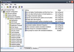 Image by Chris Trillana via Flickr

 Image by Barnaby Jeans via Flickr
 Image via Wikipedi

 Image via Wikipedia
 Image via Wikipedia


 Barrel Connector


 Image via Wikipedia

